Restoration of a Lister JP3 Generator
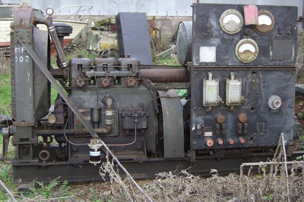
Lister JP3 15kVA Generator awaiting restoration
The generator when received was bolted to a 2 wheeled trailer, the complete weight being about 3 tons. The generator unit on its own weighs 4800lb (2182 kg). After restoration the complete unit will be mounted in the rear body of an Albion CX22S Heavy Artillery tractor with just a few inches of space to spare. At present nothing has been done to it apart from starting it to check for correct operation of the generator.
The generator is on the whole very complete. There are some parts not fitted at present such as side panels for the control board and perforated heat protectors for the exhaust system. Parts which are known to missing are an isolator switch and socket from the control board, the tool box trays, and the end of the exhaust pipe has been cut short. This will have to be modified to suit the Albion anyway.
Restoration has now started with a complete strip down. Notes were made of how everything was fitted and a manual produced to aid re-assembly. All the nuts, bolts and washers were all cleaned and threads checked and repaired where necessary, these were then sent to the electroplaters to be zinc-phosphated with a black stain finish.

All steel nuts, bolts, washers and fittings in a zinc-phosphate black finish
The crankcase was stripped of paint, degreased then primed and painted in gloss Olive Drab, the original colour of this war-time generator set. The engine was internally primed with yellow lead chromate primer originally.

Crankcase cleaned back to bare metal

Crankcase painted with primer

Crankcase painted in Olive Drab green

Crankcase painted in Olive Drab green
The crankshaft was degreased and polished ready for re-installing. It was extremely heavy!.

Crankshaft after cleaning and polishing

Crankcase with crankshaft installed
The pistons were stripped, cleaned and polished. The rings had gummed up and seized, but were taken off very carefully without any breakages. One piston was found to be severely damaged on the crown due to a foreign object falling into the cylinder, a replacement was found.

Pistons and big-end journals
The camshaft and valve-lifters were then fitted.

Camshaft and valve-lifters

Camshaft gear wheel

Camshaft pump timimg gear

Flywheel after shot-blasting
All fittings were stripped from the chassis. It was found to be in excellent condition with no repairs necessary. It was shot-blasted then primed and painted Olive Drab.

Chassis prior to shot-blasting

Chassis after shot-blasting

Chassis with primer coat
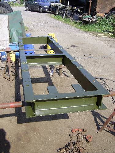
Chassis in top coat Olive Drab
The flywheel was shot-blasted then painted ready for fitting. At this stage the engine block was mounted to the chassis. The front timimng gear and cover was fitted and timing double-checked.

Engine mounted on chassis

Engine front timing casing

Engine mounted on chassis RHS view

Engine mounted on chassis LHS view
The oil pump and drive was fitted and side covers to keep out dirt and dust.

Front timing cover and oil pump drive

Crankcase side covers fitted
The generator was in good condition with the bearings like new. Just as well because replacing them could have had many problems, the slip rings would have to be removed from the shaft, this looked impossible due to corrosion and would almost certainly have resulted in damage. The commutator was polished and wiring insulation checked. It was lowerered into place with the fork-lift.

Lowering generator into place
The decompressors and lever were fitted to the side panel. The cylinder head bolts and oil tubes were fitted to the engine block.

Decompression levers and cylinder head bolts
The inlet manifold flanges were not true due to warping so they were re-faced on the milling machine. Bolting up a warped manifold may have caused it to crack later. The manifols were then shot-blasted and painted, the exhaust manifold with extra high temperature paint.

Refacing inlet manifold flanges on a milling machine

Inlet manifold after shot-blasting
The radiator was stripped. The cores were cleaned out with a rod pushed down each tube. Years of lime scale had accumulated but the core was in good condition with no holes. The cast-iron header and lower tanks were shot-blasted and painted. The radiator was then re-assembled with new gaskets and thousands of nuts and bolts! It was very heavy and had to be lowered into place using the fork-lift.

Cast iron radiator lower tank after shot-blasting

Cast iron radiator header tank after shot-blasting
The fuel tank was carefully stripped of paint without damaging the tin-plating on the steel. It was then primed and top-coated.

Fuel tank after paint stripping
The lower radiator tank complete with starting handle was bolted to the chassis and plumbed in with the gate valve. The 3 cylinder heads were fitted using new gaskets carefully aligning the link manifold between them. Manifolds and compression changeover valves were fitted after decarbonising. The injector pump was fitted with the timing checked once more. The water pump was stripped and reassembled and greased after painting.

Cylinder heads with compression change-over valves. Radiator lower tank plumbed in with shut-off valve. Injector pump and water pump with fan also fitted

Exhaust and inlet manifolds fitted with starting handle.

Radiator and slatted grill

Rear view of radiator cowling

Rear view of radiator cowling
All of the electrical fittings were carefully stripped and examined. All parts were repainted in their original colours after carefull colour matching. The electrical terminal screws and nuts are all brass and were easily cleaned and polished. The original wiring was discarded because of insulation problems. Replacement cable was bought with an authentic cotton braided covering. The wiring layout was an exact copy of the original. The rheostats were stripped and cleaned and working surfaces polsihed for good electrical contact. After some extensive electrical testing the panel was ready for installation. New rubber shock mounts were bought to support the panels which are very heavy.

Lower instrument panel rewired in cotton braided cable.

Top instrument panel

Complete instrument panel showing transformer, rectifier and rheostats
The Isenthal automatic voltage regulator was carefully stripped and repaired as necessary. It was adjusted and tested with a new electric motor fitted. The unit was re-painted in an exact colour match as the original.

Isenthal automatic voltage regulator

Main instrument panel
The fuel system was piped up ready for starting. The twin fuel filter was modified internally to accept modern paper elements much more reliable than the old felt tube types.

LHS view of engine
The exhaust pipe was quite poor, the outer skin was corroded so a new one wrapped around it and welded. The tube was cleaned out by burning excess residues with the gas torch, resulting in many explosions!

RHS view of engine

Fuel injector pump, filter and fuel pipes
Last updated: .