Purpose
10cm microwave (3GHz) mobile equipment for accurate fire control (FC) of H.A.A. artillery and was modified for use in C.A. (coastal artillery) or Field roles. Transmits continuous range, bearing and elevation of targets to the predictor.
History
An experimental set, Model A, had been completed and tested by British Thompson Houston (BTH) at Rugby in April 1941. Further trials continued in May and June at A.D.R.D.E. Christchurch. An improved and modified set, Model B, was introduced in July and an order was placed for 28 hand-built pre-production models, and a full production order for 900 sets was also placed in July. Five hand-built prototypes were built between December 1941 and April 1942, and only 8 in total by the end of 1942. Production increased through 1943 with 548 sets manufactured during 1944. Production ceased in April 1945 with a total of 876 sets delivered, 50 being shipped to the USSR. Unfortunately due to production and design difficulties, by the time the No3 Mk2 reached full production it was already obsolete. The introduction in 1944 of the US built SCR584 with auto-tracking made this highly sought after radar set the number one. However the No3 Mk2 continued in use with the services for many years after the war with many being converted for weather observation. In the early 1950's the No3 Mk2 was deployed in Germany with Independant Locating Batteries and considering its age it performed very well against the 3" and 4.2" mortars used in training. Most seem to have been demobbed from WD service during 1957/ 1958. Two have survived almost complete internally and are the subject of an ongoing restoration (see restoration pages).
Description
A steel cabin on a 4-wheeled (twin rear wheels) trailer with 3-point jacking. Contains a fixed presentation unit (P.U.) and a Rotor capable of rotation about a vertical axis. Above the cabin, the Rotor unit supports 2 parabaloids capable of being tilted in elevation. At the front of the trailer chassis is a small housing for a motor driven twin alternator set.
| Weight | 9tons 10cwt (rotor 2tons 8cwt, P.U. 19cwt) |
| Height | operational 14'1" |
| travelling 12'6" | |
| Length | operational 22'3" |
| travelling 28'0" | |
| Width | operational 15'6" |
| travelling 9'6" | |
| Wheelbase | 14'2" |
| Wheeltracks | 9'1" rear |
| 5'6" front | |
| Turning circle | 43'0" |
| Ground clearance | 9" |
| Wading depth | 1'6" still water |
| 4' + 1'6" wave(modified) | |
| Bridge class | 10 |
| Tyre size | 36" x 8" high pressure 10 stud |
| Braking system | cable operated, from tow vehicle gun cylinder |
| Access | rear and side doors |
| Climate control | heating and air-conditioning |
| Operational wavelength | 2,750-2,855Mc/s in 3 ranges* |
| A 10.56cm | |
| B 10.70cm | |
| C 10.84cm | |
| Rotor head amplifier | 60-75Mc/s |
| P.U. 1st I.F. freq | 60-75Mc/s |
| 1st I.F. bandwidth | 2.9Mc/s at -6dB |
| 2nd I.F. freq | 9.5Mc/s |
| 2nd I.F. bandwidth | 2.9Mc/s at -3dB |
| Tx power output | H.P aerial CV120 magnetron : 290kW |
| H.P aerial CV232 magnetron : 250kW | |
| L.P. aerial VC232 magnetron : 190kW | |
| L.P. aerial VC41 magnetron : 140kW | |
| Recurrence freq | 420 c/s +/- 10% |
| Detection accuracy | range +/- 25yds up to 36,000yds |
| bearing +/- 1/6deg | |
| elevation +/- 1/6deg | |
| Detection range | 27,000yds (light bomber) |
| Data transmission | H.S. and L.S. magslips |
| Designer | British Thomson Houston (BTH), Rugby and A.D.R.D.E. Christchurch |
| Trailer, 4wheel, 5ton | Taskers of Andover |
| Cabin | Metro-Cammell, Birmingham |
| Rotor and aerial system | BTH, Rugby |
| Presentation Unit (P.U.) | The Gramaphone Company |
Other manufacturers were also involved in production.
Presentation Unit
Two 6" crts (cathode ray tubes) giving Coarse and Fine ranges respectively on horizontal
time-bases. Target selected by strobe on Coarse Range tube and range determined by setting
target break to crosswire on Fine Range tube by handwheel.
Side by side display of vertical breaks on two 6" crts which are matched by operation of
handwheel.
High gear : 2 deg / turn.
Low gear : 2 turns / deg.
Antenna System
Receiver
Dipole and parasitic reflector mounted on shaft of a synchronous motor rotating at 105 revs/sec (a quarter of the recurrence frequency) about the focus of a 4' parabaloid to provide split beam D.F. fed by a concentric feeder. Dipole is displaced 1" to one side of the focus so that the direction of maximum sensitivity is inclined at an angle of 2 degrees to the axis of the parabaloid. Dipole rotation is such that, at the instants at which pulses of radiation are emitted by the transmitter, the aerial is successively in its four cardinal positions. Top and bottom aerial positions are used for Elevation measurement. Side positions are used for Bearing measurement.
Transmitter
Fixed dipole and parasitic reflector at the focus of a 4' parabaloid fed by a concentric feeder, producing equal horizontal and vertical components of radiation.
Turning Gear
Rotor turned in Bearing by Selsyn motor, max rate 10 deg/sec.
Parabaloids moved in Elevation by Selsyn, max rate 10 deg/sec.
Width of Beam
Approx 10 degrees at 1/2 signal strength.
Power Supplies
Requires 230V ac 50c/s single phase supply, demand of 7.7kVA. Two supplies labelled
steady and unsteady, usually sourced from a 15kVA Lister diesel generator.
Converted to 200V 420c/s by 2 synchronous motor driven alternators. No1 alternator provides
voltage for modulator, No2 alternator provides voltage for other circuits in the Rotor
including receiver dipole motor.
Operators
Technical operator,
Range operator,
Bearing operator,
Elevation operator.
Anti-Jamming
An A.C.W filter is fitted.
I.F.F.
If fitted, the system consisted of I.F.F. Unit Mk3 with 2 vertical omnidirectional aerials mounted on the cabin roof.
Remarks
Normally put on target by separate radar search set (putter on) such as AA, No1 Mk2 or
AA, No4 Mk3 and later the AA,No4 Mk6.
Time into action : 20 mins from halt.
Warming up time : 3 mins with spark gap modulator.
Versions
No3 Mk2/1
R.R.D.E. developed Automatic-Following modification. Did not enter full production.
No3 Mk2/2
Modified for dual role A.A. and C.A.(Coastal Artillery)
No3 Mk2/3
A.A. Command developed Automatic-Following modification. Did not enter full production.
No3 Mk2/4
Range-Doubler modification for use in meterological role. Observation of wind speeds by tracking small free balloons. Still used.
No3 Mk2/5
Dual-Role with A.A. Command developed Automatic-Follwing modification. Did not enter full production.
No3 Mk2(F)
Counter-Mortar role in F.A.(Field Artillery). The Mk2 (unmodified) was the only radar used for mortar location during the war.
No3 Mk2 pictures
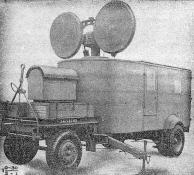
Radar, AA, No3 Mk2
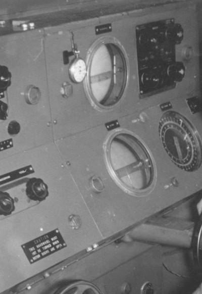
Radar, AA, No3 Mk2, Presentation Unit No 1.
© Bill Wallace
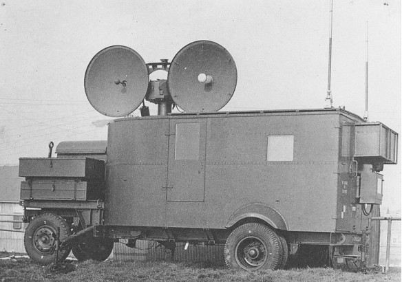
Radar, AA, No3 Mk2
References and Sources
- EMER, Telecommunications, 0 130, Radar, AA,No3 Mk2, Data Summary, Oct 1945.
- EMER, Telecommunications, 0 150, Radar, AA,No3 Mk2/4, Data Summary, Nov 1946.
- Document, DM20722/1, British Anti-Aircraft Radar Equipments.
- Radar Equipment, AA, No3 Mk2, Precis Notes, July 1948.
- Lecture Notes on Radar, AA, No3 Mk2, prepared by Radar Wing, School of AA Artillery, Dec 1946.
- Army Radar by Brigadier A.P. Sayer, War Office, 1950.
- Identification List ES311E, Presentation Unit, No1,on AA, No3 Mk2., Nov 1945.
- Identification List ES310, Rotor Units, No1, on AA, No3 Mk2., Nov 1944.
- Identification List ES834E, Radar No4, on AA, No3 Mk2., Oct 1945.
- Identification List ES1167, Panel Control Assy', on AA, No3 Mk2., June 1944.
- Identification List ES1165A, Motor, twin alternator set, No1, on AA, No3 Mk2., May 1944.
- Identification List ES1168, Panel, Gateswitch, No1, on AA, No3 Mk2., June 1944.
- Identification List ES1168, Panel, gateswitch, No3, on AA, No3 Mk2/3 and Mk2/5., 1951.
- Identification List ES1301, Box,terminal, (Plotters),on AA, No3 Mk2., Oct 1944.
- R.E.M.E. Museum Archives, Arborfield.
- Phil Judkins.
- Mike Dean.