The use of GL3 Radar in the Met Office by Bill Wallace.
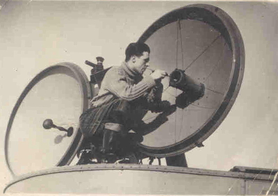
In this photo, as far as I can recall, I was checking overall sensitivity using a signal generator parked in a cubby hole to the left of the IF & Demodulator panel (that with the massive hinges!). I was looking over my shoulder at the CRT in the rotor assembly which contained the transmitter, modulator and receiver units, the last giving an IF output at 45MHz which was then fed to the IF panel via slip rings at the base of the rotor..
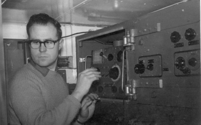
1 - Checking sensitivity using a signal generator.
Note the stopwatch which we used to take slant range, azimuth and elevation readings at one minute intervals. Then, using a slide rule, we computed the flat range, direction and height of the target (a mesh quadrant assembly beneath a hydrogen filled balloon) and passed these in real time to an ops room plotting table where wind speed and direction at various heights were measured.
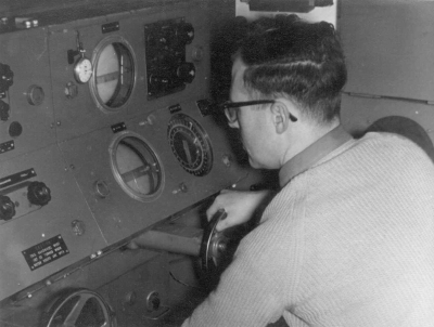
2 - Range measurement.
Although the Army used three operators (one for each control), in the Met Office we used one for range and another for both azimuth and elevation; I can't remember which one used the slide rule for the calculations but am fairly sure that it was done in the GL3 cabin. Incidentally, this was one example where manual computation was faster than using a computer! At one site (RAE Aberporth) where computing facilities were available it was proposed that they could be used instead of the slide rule. However, although computed results could be obtained in a split second, what had been overlooked was the fact that all of the observations had to be available before computation could begin because of the batch processing technique used by the computer. Using the slide rule we produced flat range, height, etc in real time..
The modulator in the rotor assembly used a "charged line" technique to produce a 1 microsecond pulse of 25kV 40A to the CV120 magnetron.
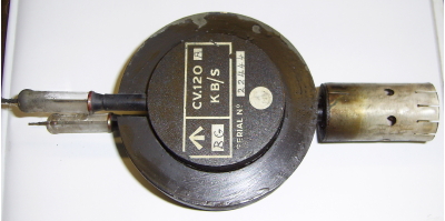
3 - CV120 Magnetron.
Copyright © 2014 www.anti-aircraft.co.uk
The early modulators used 2 x CV22 mercury vapour thyratrons but these were not very reliable (poor pulse shape, etcetera) and were replaced with a more reliable version using a single spark gap to discharge the lines and create the pulse (very similar to that used in the AA No.3Mk7).
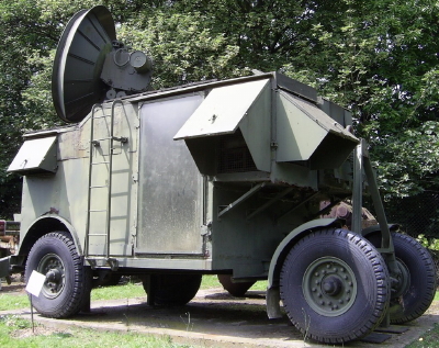
4 - No3 Mk7 radar.
Copyright © 2014 www.anti-aircraft.co.uk
Signals to and from the aerials were via air spaced coaxial feeders (solid tubular assemblies with gold plated internal surfaces). Matching to the transmitter aerial used adjustable "stubs" controllable from the rotor position (and probably set up by an Army tech WWII prior to each session). The optimum pulse shape was observed on a CRT in the rotor assembly. Signals from the Rx aerial were fed into a coaxial mixer assembly with a plug-in crystal detector (possibly CV448?) and a local oscillator signal from a CV36 klystron.
The Tx aerial used a simple halfwave dipole and reflector at the focal point of the 4 foot diameter dish. The Rx aerial was an offset dipole and reflector at the focal point of the dish shown in picture labelled "GL3 Aerial adjustment". Driven by a synchronous motor behind the Rx dish this created a nutating aerial assembly whose position relative to the focal position had four states per Tx pulse and thus gave information to the azimuth and elevation CRTs. (All of the CRTs, by the way, were VCR97s) also listed as ACR13s in parts lists.
5 - GL3 Aerial adjustment.
The Met Office used a Range Extender Unit (hence the /4 suffix to the type number) to increase detection range to 92000 yards (or possibly 96000, I can't remember). Whatever, it achieved this by delaying the Range display scan start by the equivalent of 30000 or 60000 yards. The Range Extender unit was to the right and above the Range Operator's position (possibly above the Predictor Unit which was fitted to some of the GL3's we had in the Met Office. We had no use for the Predictor Units, they were a hangover from Army use when they were used to calculate "fall of shot" I believe.
The Met Office UK upper air network in the 1950s comprised of 8 stations as follows:
Lerwick ( Shetland Islands),
Stornoway (Outer Hebrides),
Leuchars (Fife),
Aldergrove (Co.Antrim),
Ormskirk (Lancs),
Hemsby (Norfolk),
Crawley (Sussex) and
Camborne (Cornwall).
There were others at sites overseas before the "end of Empire" saw their closure as UK commitments. Additionally, there were Met Office manned wind finding sites (all using GL3s) at various Army and similar establishments thoughout the UK in support of artillery and guided weapons test ranges. To update that, the Leuchars station eventually moved to Boulmer (Northumberland), Aldergrove to Hillsborough (Co. Down), Ormskirk to Aberporth (Cardigan, W. Wales) and Crawley to Herstmonceux.
The current UK Upper Air Network sites are shown on website : http://badc.nerc.ac.uk/data/radiosonde/network.html (opens in a new window)
Copyright © 2014 Bill Wallace.